Thursday, December 30, 2010

Wiring

Well, this part of the hobby is definitely my nemesis! Though I have enough interest and fair amount of idea about electrical concepts, I definitely lack the hands on skills to do what I actually want to do. Clearly I was anticipating trouble while wiring (especially given I am using DC) and yes, one hell of a trouble it is!

Anyway, somehow I have done the basic wiring to run the trains around the layout, and quite a few tasks are still pending, but overall I am kind of satisfied... well not really satisfied, but relieved that I have finally done it!

I started with the control panel. I used Masonite board (insulation board) to construct the control panel. My wife had drawn the diagram on a black background that I pasted on the board and drilled the holes to fix the DPDTs and Peco Studs for turnout control (Yet to be wired). This is how it looks now after the primary wiring of the blocks.

By the way, this panel is totally removable. Creating this panel also required some carpentry work (again!). But this was required since I had to make the arrangement for easy portability.

Another important part that I wanted to do was avoiding soldering as much as possible because that's another grey area in my skill inventory! Especially soldering to the track. I tried this before and realized that it will be really hard for me to bring the level of perfection that I want to see. Now, to do this, I cut small pieces of thin (.1 mm) copper sheets and slide them between the track and the ties. This makes a flawless connection with the track and is very reliable with less risk of lose connection as compared to soldered joints (especially the ones I do :P). I wired the whole railroad using this method and it is working fine.


Now about hiding these copper plates, it will be pretty easy for me since most of the tracks in the port will be concealed in concrete. Moreover, if you look at the joints, it will be easy to hide these using normal ballasting.

The video below will show the first trial run:


Sunday, December 12, 2010

Brick (Hotel/Residential) building


It's really really hard to model a brick textured building in N-Scale. but they look so amazing, and fit in so perfectly with the era we're modeling, we just had to have them!! So, we eased our work a little by ordering Walther's Modulars (Cornerstone series) for Brick buildings. the front needed to look authentic, so we used the modulars for the front. The back however was mainly made of cardboard, the floor separators in the building's interior was also made of cardboard. the back has a removable panel so that future renovations, additions and alterations are easier. Once the building was assembled just in the shape and size we wanted, I got a job to do...
This is what it looked like before I got to it.


I had to colour it!!

So, I looked around for ideas and found quite a few online. Finally i settled for using old fashioned charcoal(coloured) powder mixed with a little bit of water. This highlighted the grooves on the surface, making the bricks prominent and made the job of colouring the building that much easier.


The entire building was coloured using the same mixture trying to maintain consistency of colour all around.

The roof fixtures were coloured separately and fixed.

This is how it looks as a whole now!

Thursday, December 9, 2010

Trackwork-Complete

Well yesterday I received the final shipment from US in this year! A relatively humble package of just a Peco Right hand turnout and a side mounting turnout motor.

Now as I discussed earlier, I added an additional spur to the plan exclusively for Loco parking (And now I am thinking of doubling it up as a stop for the single RDC unit that brings passenger to the port). This was not in the original plan, but I thought it wouldn't be much of a problem to fit it in.

And I was so wrong! It was probably the biggest challenge for me in laying the tracks. I had to spend hours to find the right spot for the turnout because as soon as I include the turnout, it changes the curvature of the rest of the track in that side of the runaround-and it started getting screwed badly. While trying to keep the curve broad, I was getting S curves and if I wanted to remove the S curve, the minimum radius was becoming less than 9 inches! However, after hours of struggle I finally found the right spot that would keep the minimum radius more than 11 inches without any S curves. This incident tells me that for small layout planning is ever more important than in larger layout. When you have large area at your disposal, a few inches, or even a foot might not make much difference, but for a small layout even a centimeter can screw your happiness.

Anyway, this is how it stands now:


I wanted the run around tracks to be parallel to each other, but inclusion of this turnout didn't let me do that. Even the spur is not exactly where I planned it-but hey, I am open to accept changes! :)

For some fun and testing purpose, I tried running my Life-Like Proto GP-38 on the steep grade of 6.5% in the trestle with two cars. And yes, I am satisfied with the smoothness of the grade. And this little 4 axle wonder delivers some awesome slow speed action even at 6.5 % grade! Have a look:


Saturday, December 4, 2010

Uncoupling

For some reason, I am never comfortable in the 'hands of god' concept in model railroading. In my layout I want things like switch operation and uncoupling to be done remotely from outside the layout. And yes, it has already cut a big hole in my pocket, and I am yet to acquire 9 more switch machines, but I still think it's 'required' for me to be able to do these things without taking my hand anywhere near the tracks.

Let's start with uncoupling. For the spurs it was a easy solution: under the track Magne-Matic delayed uncoupler by Microtrains (The red lines in the picture). The challenge was to find a solution for the mainline uncoupling (blue lines in the picture), because on mainlines, you must be able to uncouple only when you need it.


Now there is no off the shelf electromagnetic uncoupler for N scale which is very surprising given how much improvement we have seen in N scale over the last decade. When I was searching for options I happened up on one website that did give me an adventurous solution-bashing a Kadee HOn3 electromagnetic uncoupler kit for N scale! Here is the link to the website: http://www.aglasshalffull.org/article-uncouplers.html

It's a pretty lengthy description, so I will give a brief idea of what I had to do: First I had to narrow down the gap between the uncoupling plate to 6mm-which was quite an event given I don't have a vice. Second I had to alter the track mounting plate quite a bit to be able to squeeze it in between the uncoupler plate (which was not suggested in the website above, but I thought of giving it a try). But as it was predicted, it didn't work very well, so I had to give an additional wire support to hold the uncoupler plates parallel to the track.

Here is how it looks now:


Now there was one thing that was mentioned in the main article that I need to bend the tiny uncoupling rods in the trucks and make them parallel to the uncoupler plate. Doing so, I am unable to uncouple the cars in regular fixed magnet uncouplers. Moreover the electromagnet seem to have magnetizing my uncoupling rods in my cars and they are behaving erratically when they I'm trying to uncouple them with the fixed magnets and they have literally started 'moving on their own!'

So I would say this particular part of the project has quite a bit of hitch and I am not really sure how I am going to fix the problems-but I am sure I am going to get some solution.

Uncoupling on a curved mainline at your will!

Now coming to the other mainline uncoupling section near the bascule bridge I didn't even have the option of using a kit-bashed HOn3 uncoupler. As you can see from the plan it's on a curved mainline, right in front of a switch and there is not way I could use any conventional way of uncoupling here and for a long time I actually accepted the fact that I would have to do uncoupling using hand or a wire. But after I started building the layout, during the very first day when I was placing the tracks and the turnouts to have a feel of how and where the required things should be placed, I got an idea-which for me is brilliant!

I bought a starter pack of S.L. Enterprise's totally hidden uncoupler a few days back for a totally different purpose: modeling moving N scale vehicle without spending as much as a Faller car system. Basically it's a set of 4 highly powerful, tiny buttons of rare earth magnets on a protective iron plate. The whole assembly is pretty small: 25mm X 15mm with four magnets placing on four corners to create a small, but powerful uncoupling zone. I did a small experiment and saw that yes, placing these magnets strategically will uncouple the cars and would even let me do delayed uncoupling! Now what about uncoupling at my wish? My ready made solution was to create a simple hand driven lever system to bring the magnets closer to the tracks when required and taking them away when I don't need to uncouple!

Here are some pics:


The small iron handle at the bottom of the picture lets me 'activate' uncoupling when needed and bring it back to the default 'inactive' state when I just need to run a train without uncoupling.


Now look at the placement of the magnets-they are not really symmetrical or parallel to each other. And that is required when you have to uncouple on curved track. Not placing the magents that way will pull both the uncoupling rods in the coupled cars towards one magnet which will not let you uncouple the cars.

Now finally here is how it works:

When the uncouplers are inactive:


When the uncouplers are active:


Thursday, December 2, 2010

Trackwork

The benchwork completed, what was left was the track-laying. The planning for the layout was pretty concrete to avoid any confusion during the track laying period, but still I faced quite a bit of challenge while installing the uncouplers. Positions of the uncouplers were pre-planned and provisions were made while doing the benchwork. And these uncouplers were placed and fixed at the beginning of track laying. I have done quite a bit of experimentation with the uncouplers and will explain it in a later post.


In the picture you will see quite a few thin white cardboard pieces beneath the track in some places. Those are the masking of the switch machine holes and uncouplers. Once the scenery is added, all those will vanish.

As it is evident from the plan, tracks on this layout have a lot of curves (And Oh! I just love them!! :D :D) The yard is on curved tracks, so is the entrance and run-around. So I had to use a lot of flex tracks and curved turnouts from Peco. Talking about Peco switches (I use the live-frog one), I would say it's one of the best decisions I have made to use Peco turnouts on my layout. They are sturdy and hardy, spring loadedfor 100% reliability and gives tremendous performance for slow moving locos-even the smallest of the switchers.

All frogs have been made insulated from the following tracks as required to safeguard short-circuits. Because I have mostly used flex track, use of rail joiners were much less. I used glue and nails to fix the tracks to the bed. I am glad that I decided to use insulating board on foam for this layout. They make track laying a cakewalk!

Notice that I haven't used any additional roadbed for the track, though I had the supply of 48 ft of Woodland Scenic's roadbed. Except the entrance, the rest of the layout will have tracks concealed in concrete (I mean, not literally, modeled to be concealed in concrete) and therefore, an additional height of 4 mm would have given me some trouble filling up the space between the main surface of the landscape and the track level. I originally planned to use additional roadbed in the entrance (The town scene) but then eventually forgot all about it while laying the track! But later I thought, what the heck, I am going to expand the layout anyway... :D


As for modeling the coal trestle and the coal transfer portal, it was tough to find a solution initially. I needed a strong base which is not very thick and wide... something that can easily be modeled to be a steel trestle/bridge later on. After scratching my head for a long time, one idea did click! I used small pieces of balsa wood block (20mm wide X 10 mm thick) used in a game called Jenga by Funskool (Basically a stupid game of putting one block on top of the other, if you ask me). I used these blocks on a narrow piece of insulated board, cut as per the track plan, and joined them together to form the base for this sheet of insulated board. What I wanted was a setup that will let me model the pieces of 'Jenga' blocks as steel girder spans later. Now all I have to do is add some thin cardboard strips to model the spans, and trestle support in each joint-the coal trestle will be ready! The grade on this trestle is around 7% which is decent enough and prototypical. Plus I test run the loco on this trestle and it runs AWESOME in very prototypical, slow speed. Will post some videos later. By the way, I used sectional track to build the trestle.


To end with, a small representation of the port with the tracks on... :D :D :D


95% of the trackwork is done, only the run around and the engine house spur is left. Ordered for the turnout in Model Train Stuff and waiting for it to arrive...

I will post a separate discussion on uncoupling as I mentioned earlier, and now, all I am waiting for is to wire this up and start running trains... Oh! I will be "happier than a tornado in a trailer park!"

Sunday, November 28, 2010

Update

No, we are not sitting idle doing nothing!!!! In fact we are so busy that we haven't had the time to post!!! will be posting shortly... AND with a LOT of updates.

Friday, November 26, 2010

The port as it stands now...


As of right now, the benchwork is done. This is a small preview of what the port will look like.


Thursday, November 25, 2010

Benchwork.. contd.


The main material used to make the road-bed of our layout is insulation boards. The main reasons for using it are that they are easy to cut and shape and also that they are strong and will be able to withstand the pressure that the running trains and the scenery will apply when the entire model is up and the trains running.

The benchwork had to be made in a few time-consuming steps, details of which are as follows.

Firstly markings were made on the insulation board where the turnout motors and uncouplers would be placed. the holes were cut out and corresponding markings were made on the plywood as well.

Once the corresponding holes were made on the plywood, wood frames were attached on the ply to strengthen the insulation boards.


The support for the insulation board was made stronger by adding foam in between the wooden frames. The insulation board is cut in the shape of the port.


The port is finally taking shape with the insulation boards placed on top of the foam framed with wood.

Wednesday, November 24, 2010

A Small Addition

Added a small engine house to the plan... placed the order for the turnout as well... :) This will add a great advantage to the operation... :D

Tuesday, November 23, 2010

A whole lotta holes!!!

(An account of what's happening behind the scenes)

It was about 5 o clock in the evening when our neighbor couldn't contain the curiosity any longer. She came to find out whether or not we were having any carpentry done in the house, and if there were a lot of workmen. Carpentry work yes, workmen- er, no! Kaustav managed to make a lot of noise creating 6 holes in the plywood that wold be the baseboard to our layout.
I had gone out to the hardware store to buy drill bits only to return to find a busted drill machine! So then, we had to make do with the hand drill and chisel that we had. The noise level picked up and so did the curiosity of our neighbor. (That's when she had come in to inquire)
Well, the job did not go as planned, but it did proceed in the path we wanted to take...( I guess that's saying something!) And I helped!
The formal description of the work done will follow soon...
Mo

Saturday, November 20, 2010

Benchwork

The benchwork for this layout was simple, but it was really difficult for me to do it on my own, so I had to take help of professional carpenters.

Anyway, to start with, first a 3D model was prepared with all the dimensions:


Now the actual benchwork:

The primary objective was to make this layout as portable as possible. To do this, the table top is made removable and there are two separate rectangular structures on which the top sits. The top is made out of 12mm ply on 1 inch X 1-1/2 inch solid wood frame. There are locking system on the frame that helps it sit securely on the legs.


The cassette is made on a separate, long bench. It's a 4.5 ft. long cassette that can hold 15 N scale cars with a locomotive with ease. This limit is enough for me, and this length of train will be a "long train" from my layout's perspective as the layout is small and the traffic will be pretty slow moving.

Scratchbuilding: Operating Bascule Bridge

If you look at the track plan, it's evident that you need a lift bridge to let the ships and barges reach the quay. Now building an operating Bascule bridge was indeed challenging initially.

This bridge is a complete wooden structure with proportionate counterweight that helps in smooth operation of the bridge. The rivets are made using measured drops of acrylic paint. Some more finishing still need to be done.


For complete details on construction, please visit All Model railroading Forum. Here.

Here is a very basic under the baseboard, hand driven operation for the Bascule Bridge.


Scratchbuilding: Oil Storage


So far we have 4, but we will be making more soon... :) These are made from the cardboard cylinders that you see in toilet paper rolls! Here is a detailed construction description in All Model Railroading.

Scratchbuilding: Cranes

Well, without cranes there is no port! And so far we have made three of them-all mounted on rails. Special attentions were given towards detailing the jib:


For a detailed description on the construction, please see All Model Railroading Forum. Here.

Scratchbuilding: Ships

Well, here is a brief introduction of our pride and joy (In ascending order of size). :)


Goj: A railroad tugboat, previously commissioned for ferrying car-floats. Since the decline in the usage of car-floats, she has been towing barges.


Severus: A small cargo ship, about 30 m. Based on a prototype built in the mid 1950s, special attention was given to model the hatch and the derrick.


Sirius: An oil-tanker. Our very first ship and the favourite so far. This ship is an ancient coal fired vessel, built in 1920s in Europe. Then it was bought by an American Company in 1930s. (The ship is still in good condition and is serving small oil businesses around Wrightsville Port.)


Betelgeuse: A container ship. our very own red giant, and the largest vessel in our fleet. Betelgeuse is an old cargo ship recently remodeled to serve as a container ship to support the growing demand of modern age inter-modal transportation.


All these models are scratch built using cardboard, electric wires, toothpicks drinking straws and like. The detailed construction histories can be found in All model Railroading forum.
Coming up: A lot of boats and barges.

Monday, November 15, 2010

Introduction and Trackplan

To be very honest, I am not a very good track planner, and even if I am, I am too confused to understand what I like and what I don't. So since the time I decided to make my next layout (that was in the first half of 2008, just after moving to Calcutta from Bangalore), I don't know how many different plans I created. I spent nights boring the hell out of my wife just laying virtual tracks - I would like bits of one but the others were not acceptable, some were too big, some too small, some complicated, some too simple - and the plan(s) kept on changing.

One thing was for sure, right from the start-it had to be a port-In fact I have as much love for ships as I have for trains and was determined to combine them. So I started scratchbuilding . Started with my all time favorite Sirius-the oil tanker, then a series of ships, and tugs and cranes and bridges... Well you know, everything you need to represent a port. And, for all these months I squeezed my pocket to keep on buying things that I require to build a layout-tracks, turnouts, electronics and of course, I kept on changing The Plan.

About 3 months back, I happened upon a plan in the pile of layout drawings which inspired me to start with a waterfront layout in the first place-Ian Rice's 'Coalport, Maryland, 1941' featured in his book 'Small, Smart and Practical Track Plans'. And suddenly I realized, why I was unable to decide on anything for so long-because unknowingly I liked this plan, or better to say that loved this plan so much, that I didn't really like any other designs-neither mine, nor others. So as much as I wanted to make a plan that is unique and all created by me, I decided to go for this one... What could I have done? First cut is the deepest... :-)

Why did I like this plan? Well, this had everything I want and would love to see! Large water body, interesting switching, a draw bridge, a carfloat, a trestle, a lighthouse (LIGHTHOUSE!!!) and the most important part was that even though this was a pure switching layout, it had that depth of field, that very interesting and intriguing entry and exit. Also, if you try to imagine how the trains are going to run on this layout, you realize that even though this is a small layout, that reverse loop can crate a sense of distance that is generally not present in most switching layout.

However, I did not adopt the exact plan, rather, I could not adopt the exact plan, I have just been inspired and heavily influenced by it. Why? Several reasons-

  • Ian Rice made this plan keeping mostly hand-laid tracks and turnouts in mind-for me it has to be off-the-shelf. I neither have the time, nor the patience to hand-lay tracks. So, the plan had to be readjusted for longer turnout lengths.
  • High cost of turnouts (given that I need to import EVERYTHING from US, they cost nearly double)-so I had to reduce the number of them in the layout.
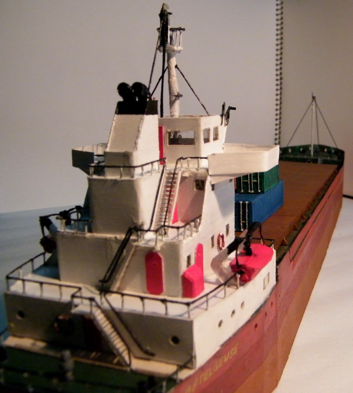
  • I decided to move at least 20 years ahead of 1941-of course because I wanted to have the option to model in Diesel, but primarily, because my wife requested for one thing that I could not refuse (or even wanted to)-A container ship! To model a container ship it was important to move the era to past '60s because before that they didn't even exist.


  • Also, the car float had to go - so far, I didn't find satisfying evidence that car-floats and container ships actually existed in harmony! I hated it at first, but then I realized that squeezing a car-float in would have made the layout really clumsy for what I have in mind, and moreover, I would have something to look forward to extend the layout in future! Of course, if by then I find enough evidence that car float and container ships go well together.
  • Instead of a Warehouse, I decided to go for a Grain Transfer facility where grain barges bring the load in, then are unloaded by pneumatic unloaders which is then transported out of the port by the grain hoppers.
  • The only part where I didn't agree with Ian Rice's plan is putting the trestle right in the middle of the layout. In my mind that would actually create obstruction to the objects behind it and the visual effect might be a little compromised. So I decided to pull that to the far right of the layout-where the industry stands in Mr. Rice's design. This will also give an added advantage over the original plan, an over and under action!
  • I removed one runaround (the top one) in the original plan.
  • Added a small boat yard in the left corner.
  • I am planning to build a small tunnel in the background hill. I personally like the effect of trains appearing/disappearing through a tunnel and I think it increases visual effect to a great extent.
  • I gave the trains a longer run and gave myself a chance to model a small town scene at the far left.
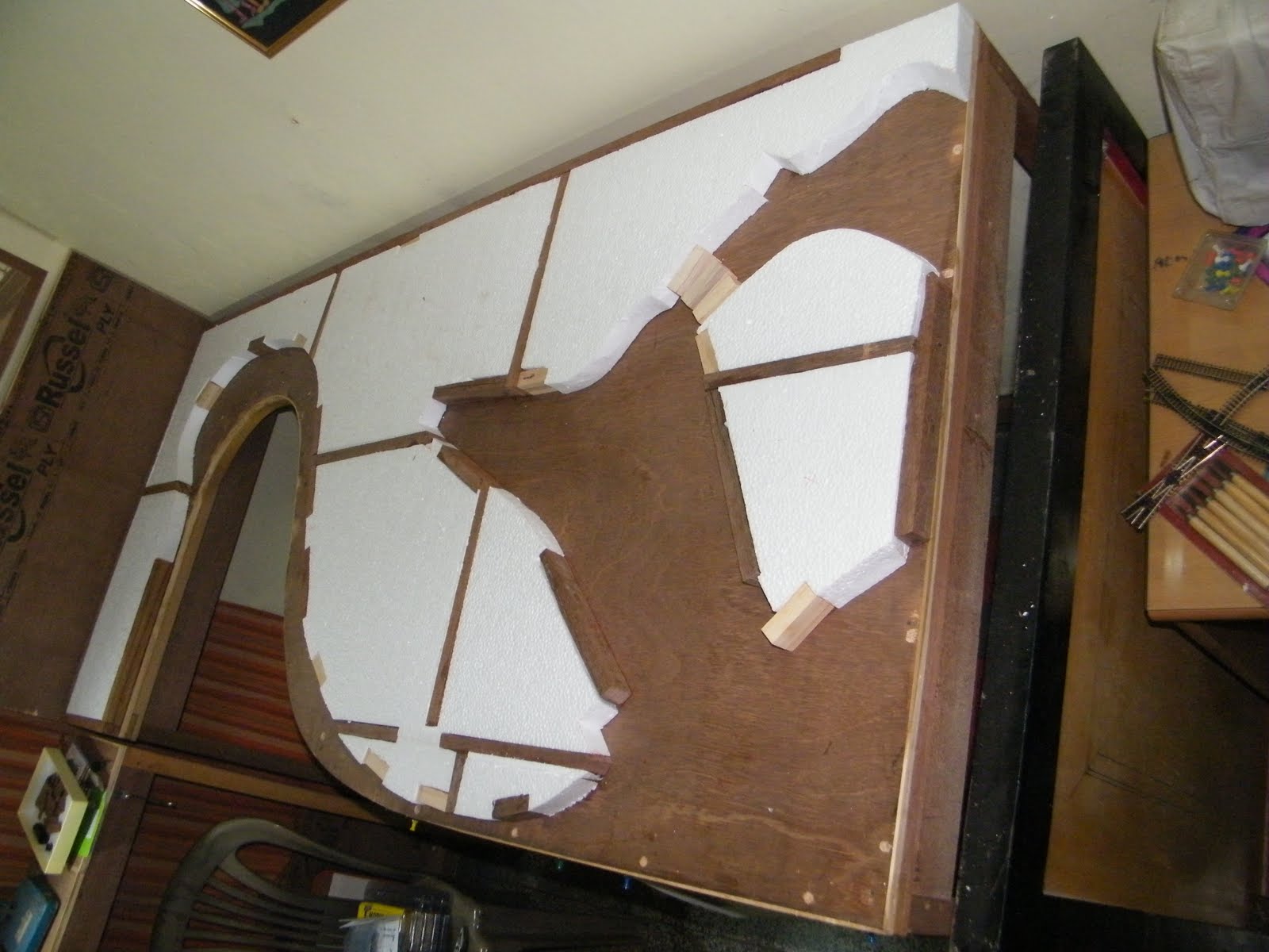
Layout Statistics:
  • Size: 6' X 3' with cassettes feeding the trains from the far left
  • Benchwork: 12mm ply on 1"X 1.5" wood frame-totally portable
  • Track: Code 80
  • Min Radius: 11"
  • Grade: none (I am keeping the coal trestle grade off the main list as it's a special operation for the railroad. Trestle will have at least 6-7% grade)
  • Era: 1960-1970
  • Motive power: Diesel and occasional steam
The layout will also have complete remote switching and uncoupling, as well as automated signaling system.

As of right now, the benchwork has been completed (to be discussed in my next post), the necessary materials and tools have been gathered, the workspace cleared and I have a long Thanksgiving vacation which I plan to put to optimum use in formally starting the project!!
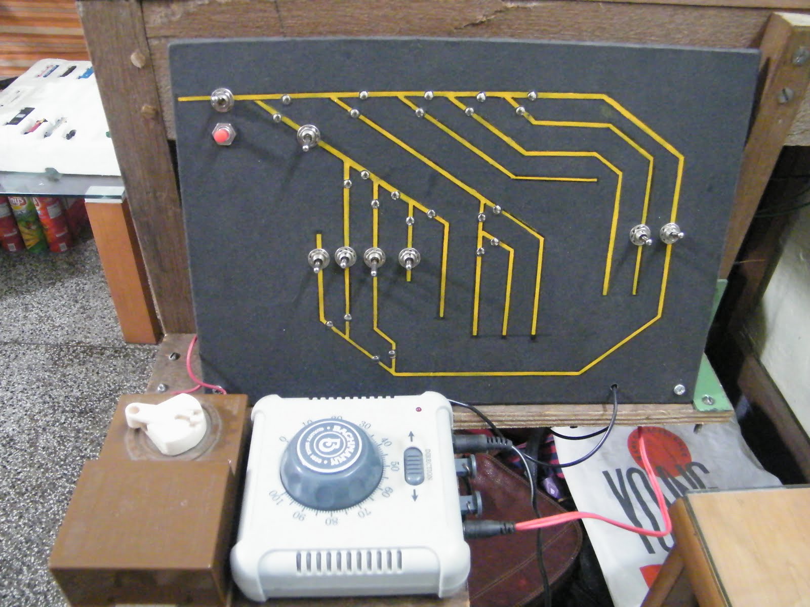