Friday, July 18, 2014

Container Crane Building Post - 4

The next step was to complete the spreader.

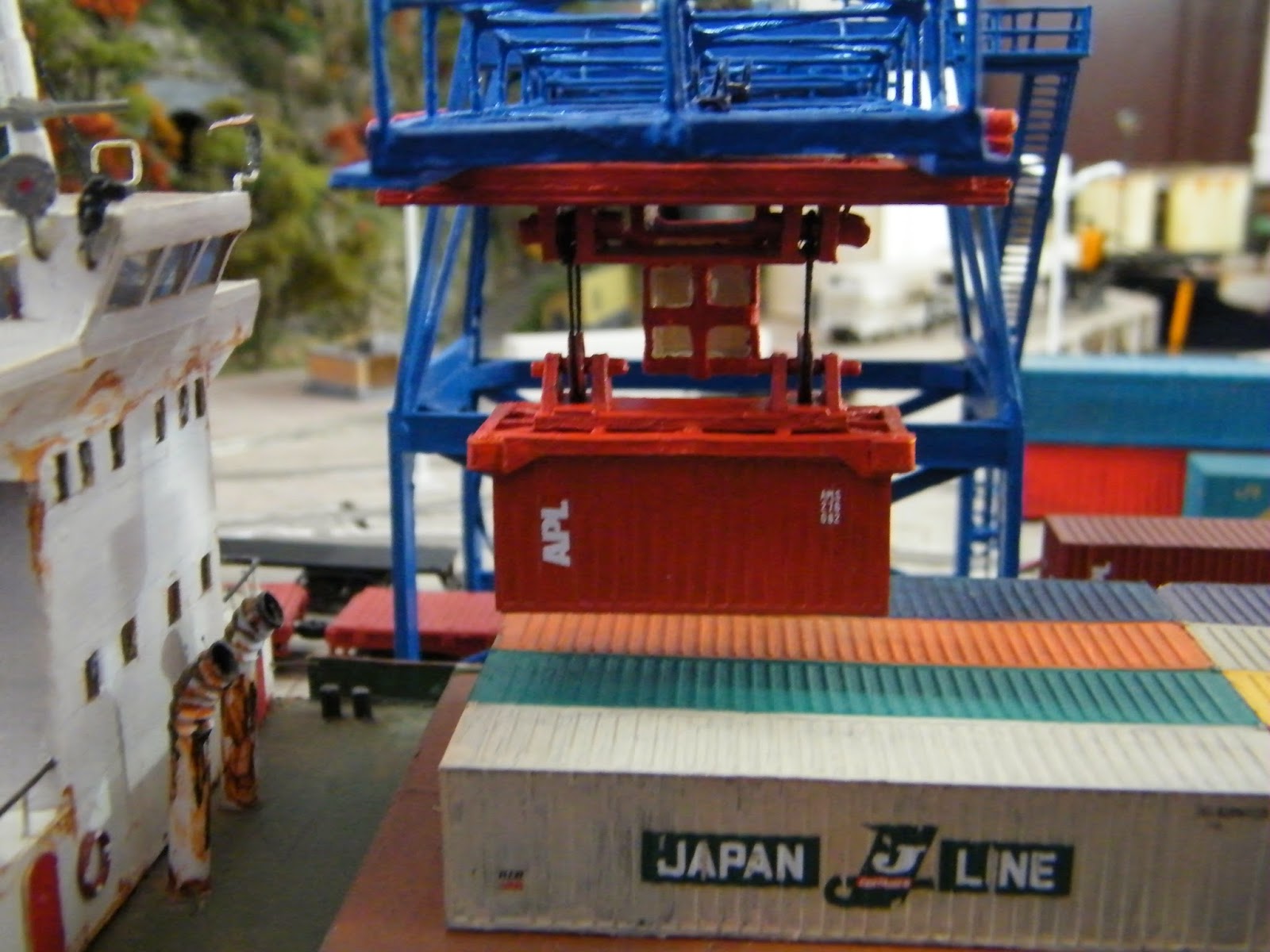
The Spreader, as shown in the second part of this build thread, will be movable to increase variety of positions during photography session. Also, I had to arrange for a mechanism so that I can keep changing the containers from time to time.

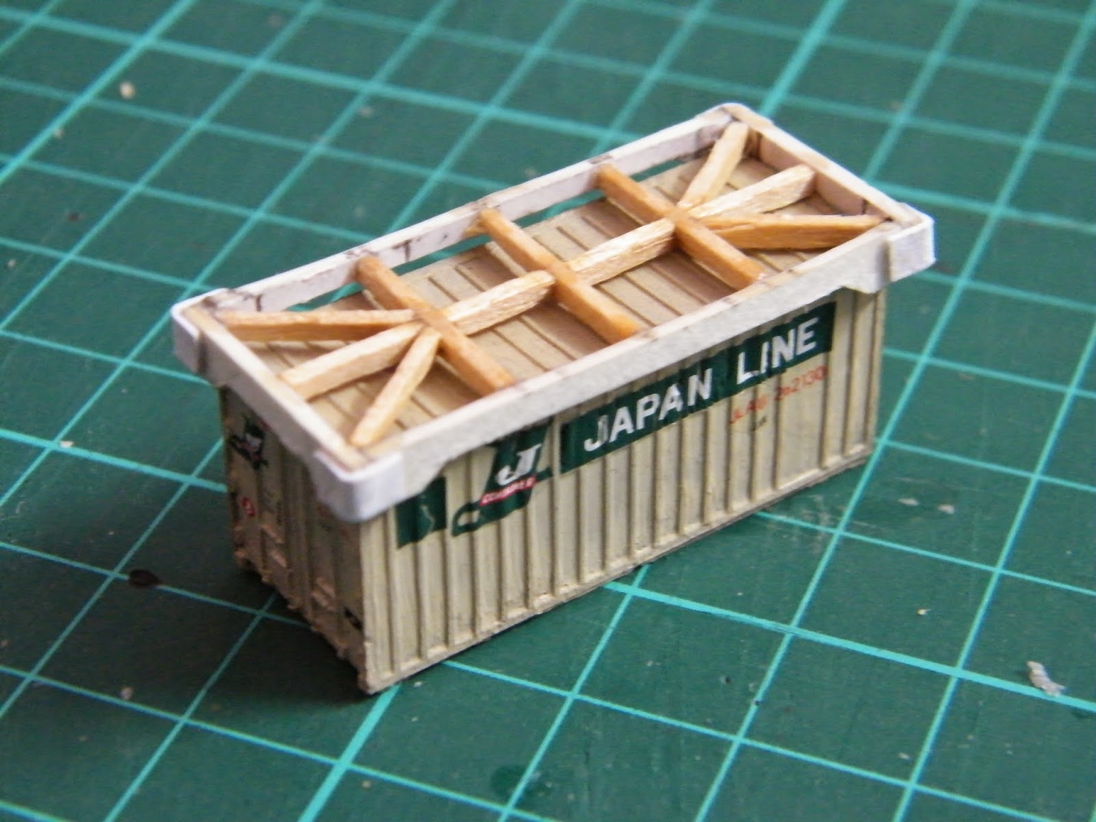
So first, I created a cardboard frame that can simply hold my 'Fine N Scale' 20' containers from top and maintain a good grip throughout. The trick is that the inside dimension of this cardboard frame is just a tiny fraction larger than the outside dimension of the container - to the naked eye it is actually the same unless you use a caliper to measure it.You might ask how I did it without using the caliper though - simple when I drew the dimension on the cardboard with a sharp pencil, I'd cut the cardboard on the 'outside' of the line, not on it - takes a good degree of precision, true, but given I am working this stuff for so long, I think my motor skills can take those challenges! :-P


Once I tested the effectiveness of the frame by lifting and shaking it several times while it holds the container, I started building the support. I used some really old stock of Micro Engineering wooden ties.


Then I started working on the pulleys. I went for the more simplistic design add just two pulleys on two sides - given we are talking about really first generation container cranes, I think that is still prototypical. I took a couple of Grandt Line small wagon wheels, curved groove along the edge, and voila - I have my pulleys! It was then just a matter of creating simple housing for them and attaching them the the spreader.


Next step was to create the hoist mechanism on the trolley. I went for a covered approach this time, more for stability, and for the fact detailing of that part will be hardly visible. As you can notice, I had to use 'tying' it up with the trolley to ensure durability!


The next step was to create the cabin. I drew the complete dimensions on a cardboard first and then cut it precisely using my hobby knife. Once done, just folding it and gluing it in appropriate places is all that you need to do.


Next step was to paint all the components red, cut OHP sheets of appropriate sizes and create the glass cover of the cabin, and then finally put everything together to finish the assembly. Notice that I still have interiors to complete inside the cabin (awaiting orders), and kept the provision of removing it.


Finally, here is the complete mechanism to move containers to and from the ship:


Coming up - final bits of detailing - counter weight, beam draw mechanism and the links. Then I'm done with this one! :)

Friday, July 11, 2014

Container Crane Building Post - 3

The next was the electrical connections for the light. As always, for lights on the structure, I always try to be as flexible as possible and hence try to avoid soldering. The reason being, once the structure is built changing a burned bulb is hell of a task and possess much higher risk of damaging the structure itself. Often in N scale it's easier said that done, just because the size of the structures are too small and making removable 'plug' points for LEDs might make the arrangement look out of proportion - but given this one is a relatively big structure, I decided to go for it.

The first challenge was the folding beam - the connections should hold throughout the up and down movement of the beam. I created a pivot by drilling a tiny hole in a copper strip and pushing a 22 gauge single strand wire into it - it should be a tight join to maintain constant electrical connection. The main connection to the power were soldered to the copper plate. There was another distribution to the fixed part of the beam.


As for attaching the LEDs, I used 1mm X .355mm copper tubes - soldered the input power lines to them and put the LED lead wires into the other side of the tubes, as shown in the above pictures. I made arrangements for a total of 4 LEDs across the beam.


Once the construction of the beam was over, I moved into completing the tower. Added styrene ladders and railings (Evergreen Models). Used Gold medal models ladders and created a ladder cage by making tiny rings made out of single strand electrical wires and thin cardboard strips.


The next step was to complete the painting. I decided to go for Blue as so far there is no blue structure on the layout, and it is a very common color for container cranes. Below some photos:


Coming up - the last of components - counter weight, operating pulleys to retract beam, and the trolley to move containers.

Tuesday, July 8, 2014

Container Crane Building Post - 2

The next step was to create the truss support on the main beam. Also, I made some changes in the design - initially, I thought of going for a fixed beam crane, but then I thought that if I make the beam fold upwards I can create different scenes with different position of the beam, hence decided to go for the retractable one.

So here are the photos of the brass tube truss support on the main beam - used 1/32 X .006 inch (0.81mm X 0.153mm) brass tubes from Special Shapes Co. I used 22 gauge single strand wires inside the tubes for reinforcements, and connecting the joints.


Next step was to design the trolley. given I started making this crane to simulate both working and non-working conditions, I decided to make the trolley movable as well. As for the basic structure of the trolley, used cardboard, pins, and small pieces of 2mm X 1mm styrene tubes as wheels.


Sunday, July 6, 2014

The last of the big cranes...

Long pending, as you all know. I have been planning to get into a new scratchbuilding project for a long time, and other than the new buildings, didn't have the opportunity to look at something more complicated. So this week when I had some time and the chance to start something new, thought of completing the last of the big cranes on Wrightsville Port

My research shows that one of the first proper container portals in the US was in Seattle in late 1960s. May be there were more, but there was not enough research material (articles and photos)online  for me to refer to. Additionally I did find a proper N scale drawing of the first generation Paceco 32.5 ton cranes and that was pretty helpful too. Here are some of the photographs and the drawings that I am referring to:


Now the challenge is the dimension - honestly, I had 'forced' the container portal in my design of the Wrightsville port, hence I could not allow for as much space as it's required for a true container portal, even for N scale. Hence the dimensions had to be readjusted as below:


Now, clearly the ratios will not fit to replicate the actual crane, but all that I can do is to bring it as much close to the prototype crane as possible - I know it's an unrealistic expectation to replicate a prototype that never existed!

So here is what I accomplished so far -

First the basic structure of the tower:


Then the basic structure of the tower and the beam:


Finally with all the basic truss supports and cross beams for strength:


Coming up: Complete detailing of the beam and the tower, including stairs and ladders and the lights.